Quite a while ago I rescued a barely used BenQ MH720 DLP projector with ~180 lamp hours from going to the trash because it had a dark shadow on the left side of the screen. However, I never took the time to have a closer look at the problem, and it sat on a shelf for years - until this weekend.
Upon turning it on, I was greeted with the following image (sorry for the lack of projection screen, I did not have a big enough white wall close by my work desk):

What was curious is that in the top left corner, the browser tabs, url bar and bookmarks are still faintly visible.
The lamp Link to heading
Overall, the image seemed well illuminated, so the lamp must still work. Still, I took it out to have a closer look. The lamp itself seemed perfectly fine to my untrained eye, so I decided to play with the angle alignment screw on the lamp cartridge to see if that made a difference.
This led to a very interesting discovery - the image suddenly became a lot brighter, so much in fact that it almost hurt my eyes and I got scared that something was wrong and would cause further damage. Luckily, a quick google search told me that the lamp angle should be set for maximum brightness of the projected image, otherwise the powerful beam might hit the edge of other optical components and damage them.
Tracing along the supposed light path, it seems that damage has indeed occurred from misalignment of the lamp:

At that point I had no idea what I was looking at, but what I saw did not seem right. The damaged part was not accessible from the cartridge compartment, so disassembly was necessary - another first for me.
Disassembly Link to heading
Taking apart a projector was a scary undertaking, as I did not know whether I would encounter delicate optics that require special knowledge to deal with. Luckily for me, all the sensitive optical components are enclosed in one single, solid cast iron part and this turned out to be more or less just a standard electronic device repair. At this point I should give credit to FixitFrank on YouTube, whose videos on projector repair helped me a lot to pull this of.
With that out of the way, lets get into the nitty-gritty of this repair. Here is the general schematic of a DLP projector:
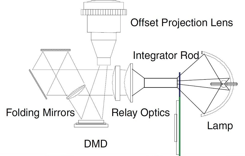
The light starts at the lamp, passes through the color wheel and the light tunnel (“Integrator Rod”), then through some lenses (“Relay Optics”), gets reflected (“Folding Mirrors”) onto the DMD (digital micromirror device), and goes out through the projection lens from there. We are going to focus on the color wheel and light tunnel components, just before the main projection unit that contains all the lenses and mirrors. Both the color wheel and light tunnel are fairly fragile components made out of glass, and require delicate handling. Same as with the lamp, avoid touching them with bare fingers to not leave behind any fat stains that might cause damage. If you do, use isopropyl alcohol to carefully clean them.
To get to the light tunnel, the color wheel needs to come off. But the color wheel is fixed to the main unit, so the main unit has to come out in its entirety. Here you can see the main unit with the color wheel and light tunnel already removed. On the left is the cooler for the DMD, and on the right is the projection lens with zoom and focus rings accessible from the outside:
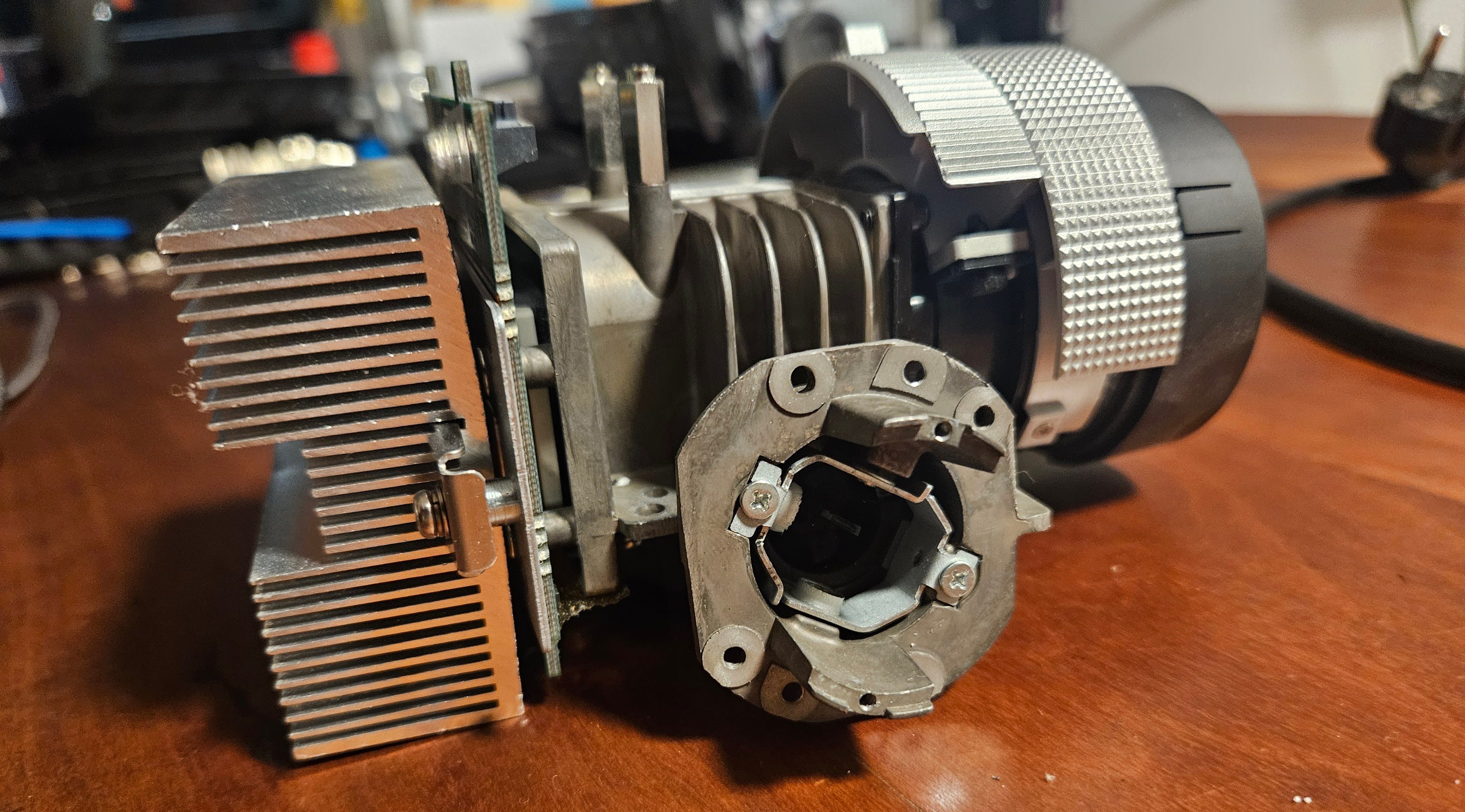
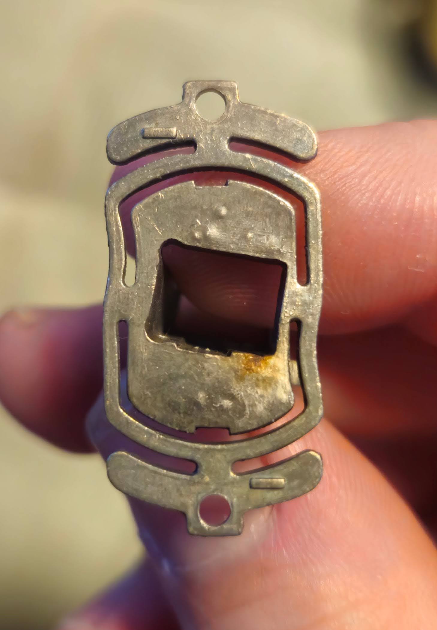
The light tunnel sits inside the small tube in the center of the picture, held in place by two springs and two screws for x-y-axis adjustment. The color wheel is screwed onto the cast iron tube that contains the light tunnel. Above the color wheel, you can see a row of pins that help guide the lamp cartridge into correct alignment and hold it in place:
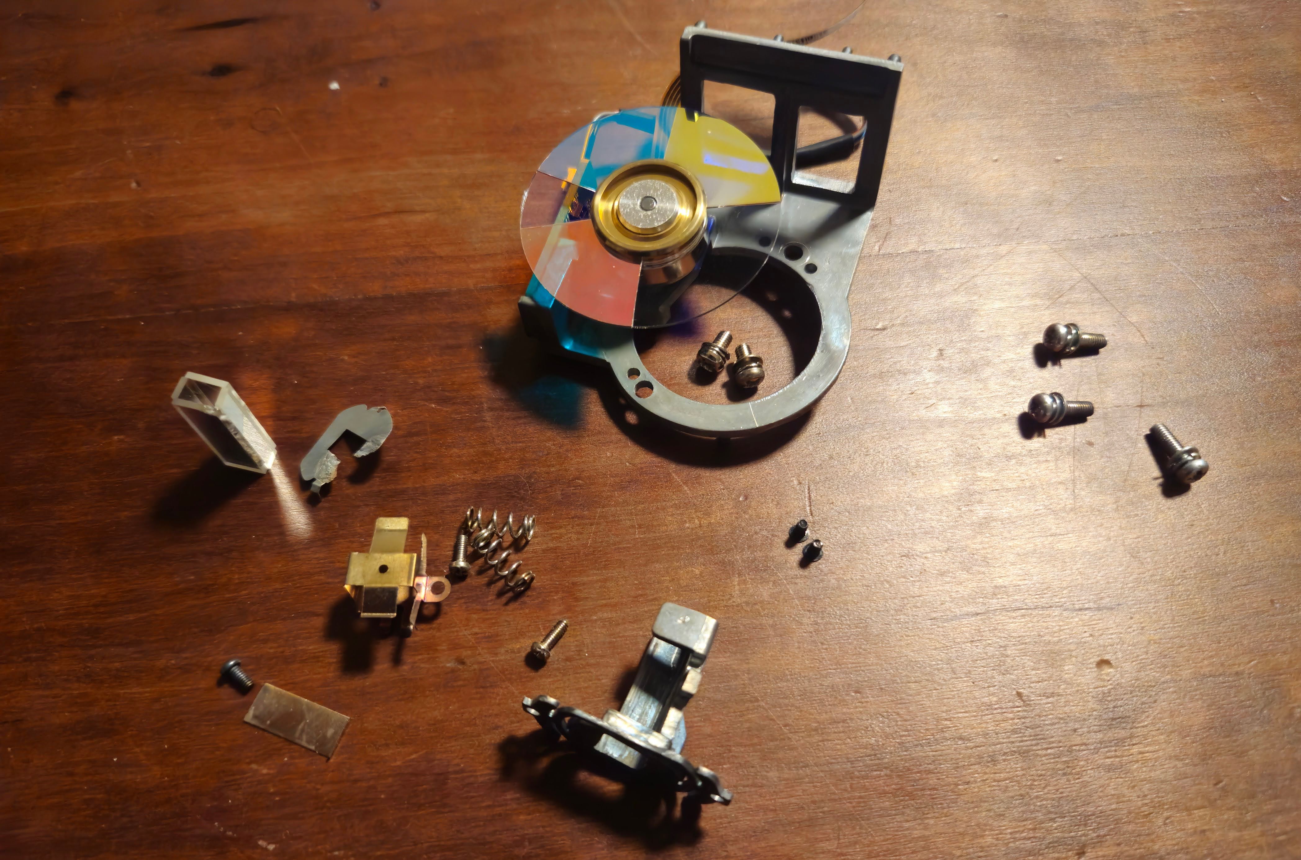
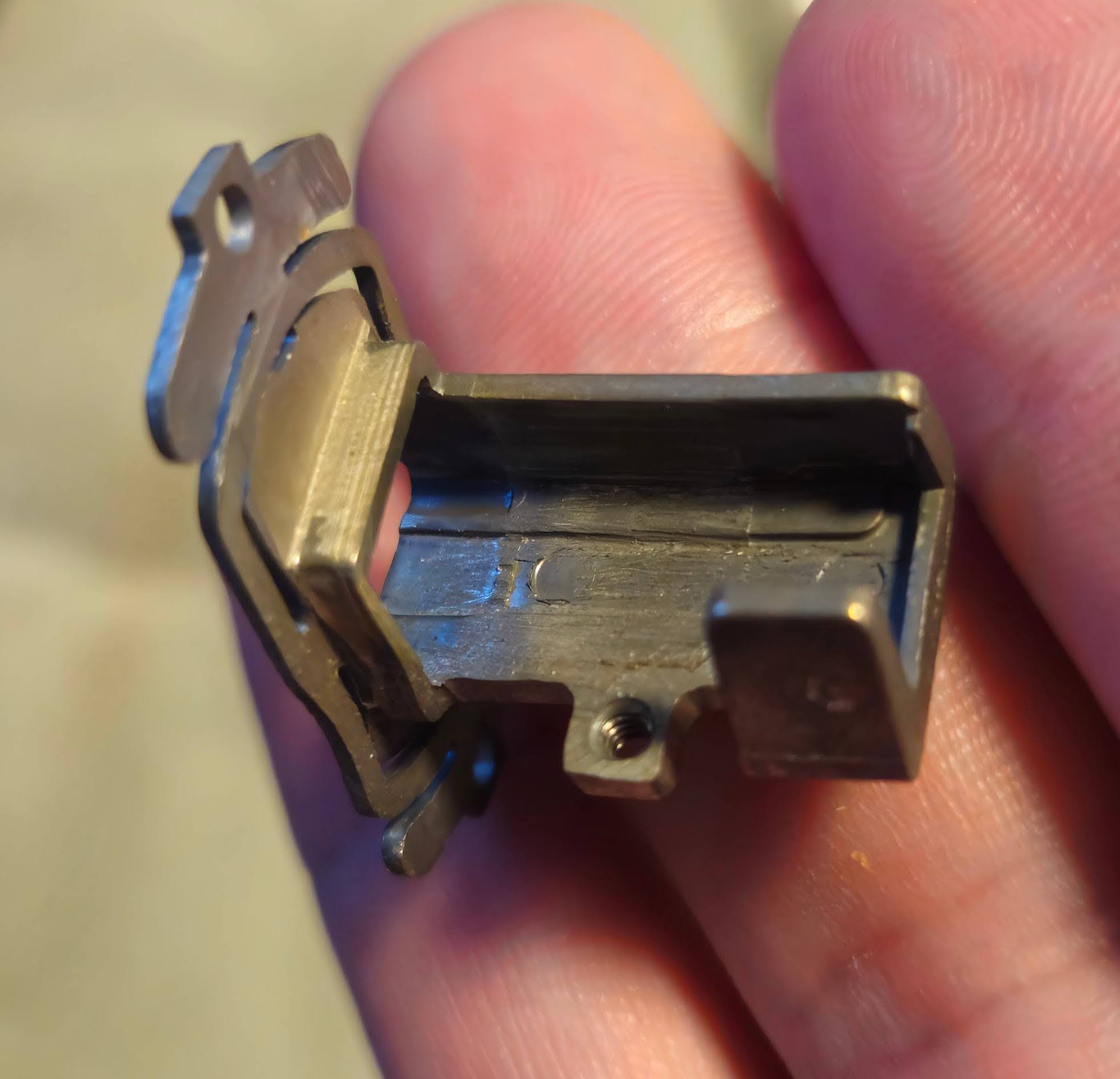
Below, you can see the component that contains the actual light tunnel, and provides compliant mounting points for adjusting the direction of the light tunnel:
The root cause Link to heading
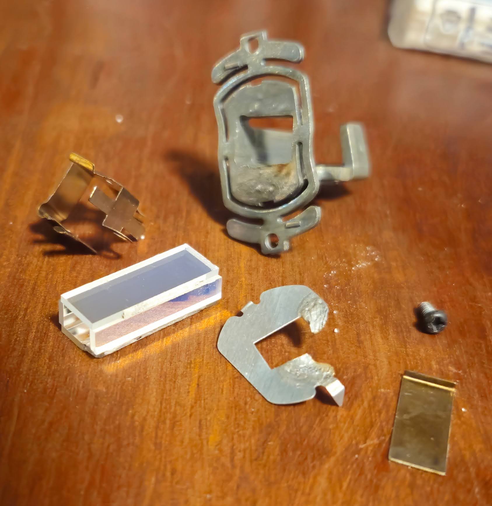
After taking all of it apart, the damage becomes more clear: it seems that the lamp misalignment that we discovered earlier burned away parts of something that looks like a heat shield. Then, the beam must have heated up the light tunnel assembly, and thermal expansion caused to be out of alignment. Additionally, even the corner of the glass of the light tunnel seemed to have been molten under the extreme heat!
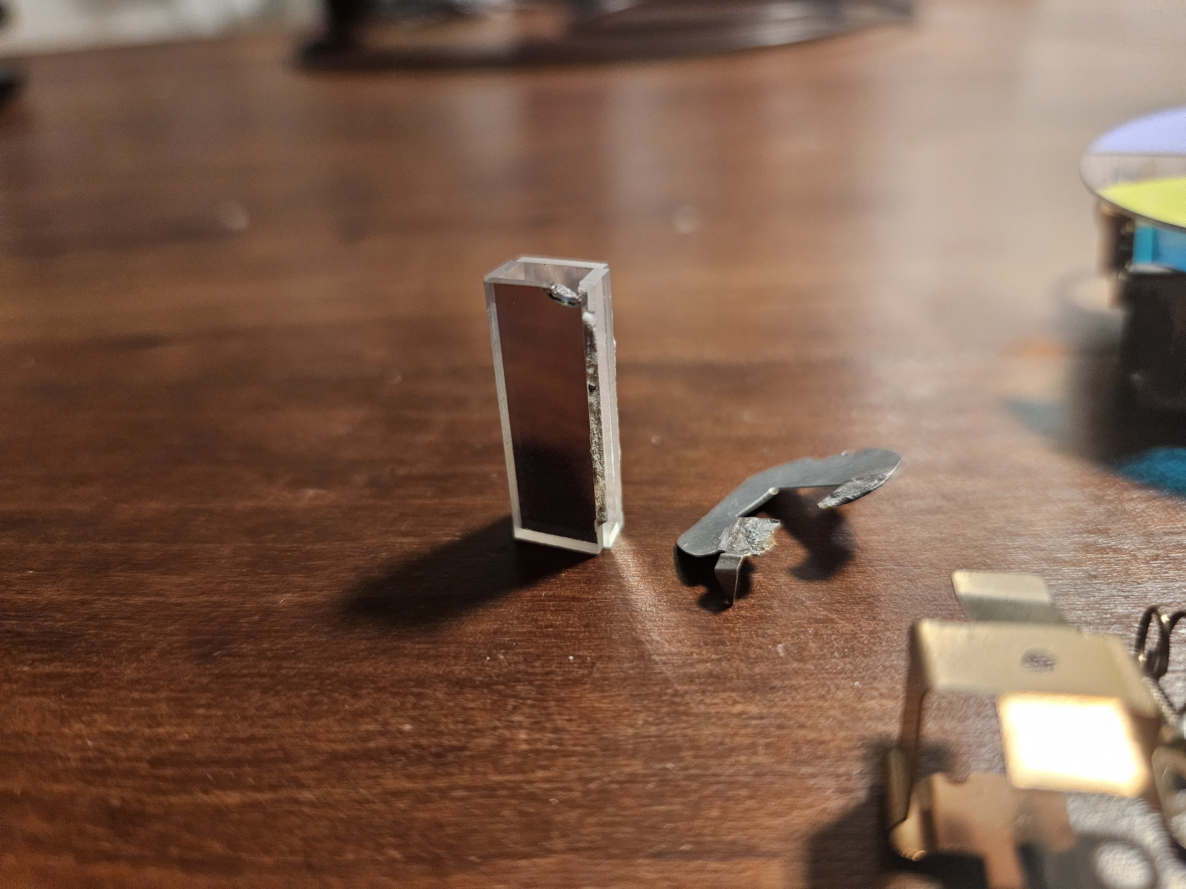
The light tunnel consists of four flat optical mirrors, glued together with some sort of extremely heat-resistant cement. Unfortunately, the integrity of the cement was also compromised, and one of the four sides became loose and misaligned during disassembly.
Replacing the light tunnel Link to heading
Re-gluing the light tunnel would have required specialized equipment to get the distances and angles right, so instead I decided to try and order a new one online. After doing some research, I found a seller on ebay that has a variety of light tunnels in stock (https://www.ebay.com/str/lampbook). None mentioned my projector model as a compatible device, but an offer for a BenQ TH683 seemed to match the exact dimensions I was looking for. The seller was very helpful and confirmed that everything should be fine if the dimensions match, since in the end it’s just a bunch of mirrors. US $15.00 excl. shipping and two weeks later I had a new light tunnel in my hands, and could finally start putting the projector back together.
Assembly and alignment Link to heading
During reassembly, the light tunnel needs to be aligned correctly - this step is correcting for the issue that we saw in the very beginning. The screws for aligning the light tunnel are located on the outside of the cast iron tube that the light tunnel sits in. The up-down adjustment screw is easy to reach from the top, but the left-right adjustment screw is difficult to reach when the device is assembled so that it can be powered on. At the same time, a powerful light source is required to verify the correct alignment. To work around this, I used the strongest flashlight I could find, held it against the light tunnel and looked into the projector lens where now a faint outline of the rectangular DMD was visible. This was a bit tricky because it would be done easier with three hands, but in the end I was able to get left-right axis adjusted so that there were no dark shadows on either side. The up-down adjustment was then done with the projector lamp after it was fully assembled.
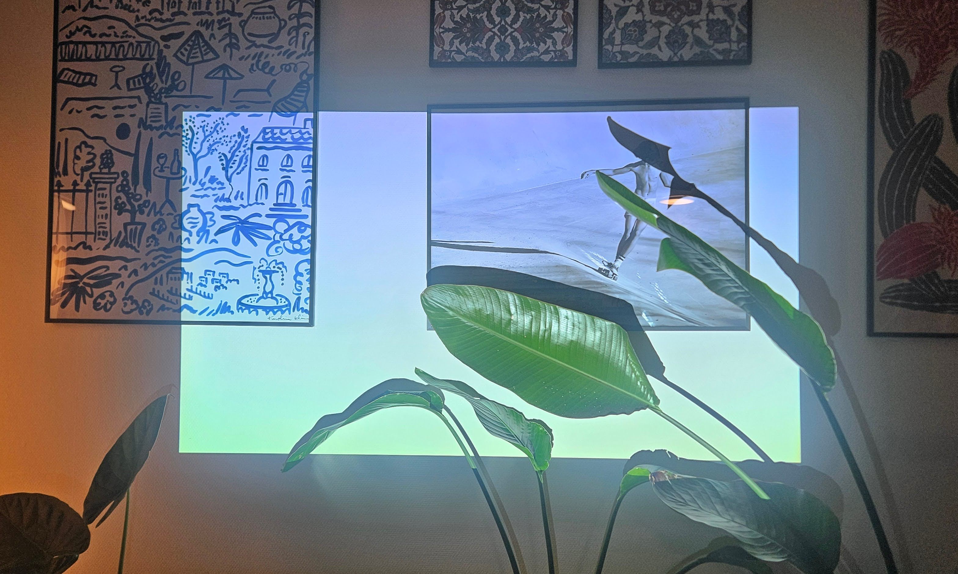
The very last step was to again align the projector lamp, now that the light tunnel was seated and aligned correctly. Bonus fact: The projector was displaying a pure white image in this picture. DLP projectors with color wheels project each color for a single frame in sequence. Combined with the shutter speed of a camera, the individual colors can become visible, which is what happened here.